SRS PTC10 Temperature Controller
Notes below are for the SRS PTC10 programmable temperature controller. This is primarily used at 11-BM to monitor and control the temperature when using resistive heating coils in the flow cell sample environment.
UserControl Functions
def QPID_SetTemp
def QPID_SetTemp(rampRate=0, setPoint=0, Run=True, DeltaRampRate = 0.1, DeltaSetPoint = 2.0, WaitFlag=False, DeltaTemp = 2.0, MaxWait = 120):

   Sets QPID values for temperature control
   rampRate, in deg C/min; default (0);   rampRate is set BEFORE the new setPoint
   setPoint, in deg C; default (0)
   Run, toggle PIDmode, default (True): Use the single command QPID_SetTemp(Run=False) to disable QPID output
   DeltaRampRate, in deg C/min; default (0.1); window for confiming that rampRate is correctly set
   DeltaSetPoint, in deg C; default (2.0); window for confiming that setPoint is correctly set
   WaitFlag, flag to invoke "wait for temp"; default (False):
   DeltaTemp, in deg C; default (2.0); window for confiming that temperature when WaitFlag = True
   MaxWait, minutes; default (120); time limit for confiming that temperature withing DeltaTemp when WaitFlag = True
example code
QPID_SetTemp(rampRate=20, setPoint=100, WaitFlag=True)
QPID_SetTemp(rampRate=2, setPoint=500, WaitFlag=False, MaxWait = 480)
QPID_SetTemp(Run=False)
Networking
SRS PTC10 Serial # 92182
MAC = 00:19:B3:06:00:B6
IP = 164.54.111.19
Hostname = 11bmptc10
Manuals
Hardware
In addition to the default I/O, the 11BM PTC10 also was ordered with
- Slot 1 = PTC430 DC output card delivers up to 1 A of current at 50 VDC,
- Slot 2 = PTC330 K-type Thermocouple Card (x4 inputs)
Software
SRS PTC10 may be controlled remotely using Guy J. 'qpid' software via IP network communication. USB and RS232 (serial) are also possible, but Guy has found serial comms to be a bit unreliable.
NOTE: when using 'qpid' specfic names are required for the input and output control variables. They can be renamed using the PTC10 touchscreen.
- input thermocouple (typically slot 2, TC#1) must be named TC
- output control (typically slot 5, A) must be named Control
User Notes
The notes below are specifically for using the PTC10 at 11-BM with the TEXIO PD18-30AD Power Supply for resistive heating coils in the flow cell sample environment, but may also be more generally useful.
The PTC10 may be controlled and configured using the touch screen.
NOTE : User's must manually press the OUTPUT ENABLE red button to enable (press twice) or disable (once) any output. When the red LED light is on, PTC10 outputs are enabled. For safety reasons, there is no software control of this button.
Select Panel
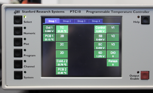
The PTC Select Panel screen is shown below. Under the Group 1 tab, both the input TC and output Control channels have been selected (light green). This determines which items are displayed on subsequent screens for the selected active group tab (#1 in this case). One can select different items for other groups (#2, #3, or #4)
Plot Panel
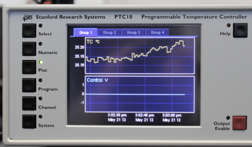
The PTC Plot Panel screen is shown below. There are several different plots to select, and one can zoom and pan by using the touchscreen.
Channel TC Panel
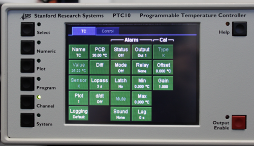
The PTC Channel Panel, TC tab screen is shown below.
- NAME: defines the channel name (should be TC)
- PLOT: defines how this is displayed in the PTC10 plot panel
- LOPASS: apply a lowpass filter to TC temperature readings, should be the largest time value (in seconds) that is still less than the
amount of time for heater to respond (leave at 3 S)
- Alarm or 'Cal' options are not needed.
Channel Control Panel
The PTC Channel Panel, Control tab screen is shown below.
- NAME: defines the channel name (should be Control)
- LOWLMT: low output limit (set to 0 for use with D18-30AD Power Supply)
- HI LMT: high output limit (set to 10 for use with D18-30AD Power Supply)
- UNITS: defines control output units (set to V for use with D18-30AD Power Supply)
- IO TYPE: should be Set Out
- PLOT: defines how this is displayed in the PTC10 plot panel
PID Options
- MODE: defines the PID mode, set to ON (ON/OFF paired with 3rd button down in first column). The PID ON/OFF mode can be toggled remotely.
- INPUT: defines the feedback input for PID control (set to TC for use with D18-30AD Power Supply
- SETPOINT: defines next setpoint, device will ramp to that setpoint at the ramp rate defined below (can also be set remotely)
- RAMP: defines the ramprate in deg/seconds
- RAMP T: current target setpoint as device ramps to final setpoint.
Tune Options
- Mode = toggles auto, manually, or no tuning. See manual or staff. Should be left as OFF for most users.
other terms here define parameters used for auto PID tunning.


