Difference between revisions of "TEXIO PD18-30AD DC Power Supply"
From Ug11bm
Jump to navigationJump to search (Created page with "Notes below are for the TEXIO PD18-30AD DC Power Supply. It is primarily used at 11-BM to provide power for resistive heating coils in the flow cell sample environment. == Manua...") |
|||
| Line 3: | Line 3: | ||
== Manuals == | == Manuals == | ||
[http://s11bmsrv1. | [http://s11bmsrv1.xray.aps.anl.gov/staffdocuments/TEXIO_PD18-30AD_DCPowerSupply_Manual.pdf TEXIO_PD18-30AD_DCPowerSupply_Manual] | ||
== Specs == | == Specs == | ||
Latest revision as of 18:35, 12 March 2014
Notes below are for the TEXIO PD18-30AD DC Power Supply. It is primarily used at 11-BM to provide power for resistive heating coils in the flow cell sample environment.
Manuals
TEXIO_PD18-30AD_DCPowerSupply_Manual
Specs
- 0 - 30 Amps
- 0 - 18 V
- 0 - 450 Watt
Operation & Settings
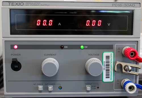
Front Panel
- Turn On PD18 Power
- Adjust Voltage/Current Settings/Limits if needed (see below)
- For 11-BM resistive heating coils, connect matching Blue-White & Red-Red lead wires (as shown below)
- For 11-BM resistive heating coils, isolate ground connection (as shown below)
- ENABLE OUTPUT press OUTPUT button, enabled = red light ON
- CC (red) and/or CV (green) lights indicate output is limited by Current Limit state (CC) or Voltage Limit state (CV)
Image of Front panel of TEXIO PD18-10AD DC Power Supply
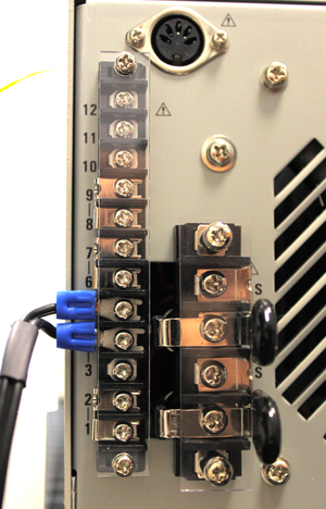
Back Panel
Image of Back panel of TEXIO PD18-10AD DC Power Supply
- #1 - 12 are input terminals for remote control and series/parallel operation.
- For control by external voltage (i.e. SRS temperature control), connect voltage across pins 4 - 5 (as shown below)
- External voltage should be 0-10 V, with impedance ~ 10 k Ohms
Voltage / Current Settings
- Manually set by turning big Current & Voltage Knobs
- When controlling remotely, these values will set the V & I limits
- To check setting, press V/I CHECK, then check value and adjust if required.

