Difference between revisions of "Hot Gas Blower (Cyberstar)"
| Line 66: | Line 66: | ||
See also | See also | ||
[http://link.springer.com/chapter/10.1007/10832182_445 Landolt-Börnstein - Group III Condensed Matter Volume 41A1b, 2002, pp 1-17, Group IV Elements, IV-IV and III-V Compounds. Part b - Electronic, Transport, Optical and Other Properties, Group IV Elements, IV-IV and III-V Compounds. Part b - Electronic, Transport, Optical and Other Properties, Silicon (Si), lattice parameter, thermal expansion] | |||
[http://link.springer.com/chapter/10.1007/10832182_445 Landolt-Börnstein - Group III Condensed Matter Volume 41A1b, 2002, pp 1-17, Group IV Elements, IV-IV and III-V Compounds. Part b - Electronic, Transport, Optical and Other Properties, Group IV Elements, IV-IV and III-V Compounds. Part b - Electronic, Transport, Optical and Other Properties, Silicon (Si), lattice parameter, thermal expansion | |||
Revision as of 20:21, 10 March 2014
About
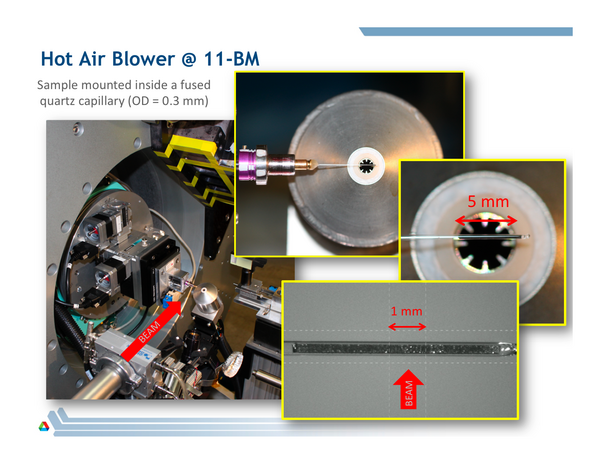
11-BM has a dedicated Cyberstar Hot Gas Blower. This can be used to heat small diameter capillary samples from ambient temperature to ~ 950 °C
Temperature Range and Ramp Rate
- Heats small diameter capillary (< 1 mm diameter) samples from ambient temperature (25 °C) up to ~ 950 °C
- Max ramp rate on heating & cooling is 5 deg C/min (300 C/hour). Below 300 °C a faster ramp rate of ~ 10°C/min may be used.
Users should plan experiments to incorporate these limitations on sample size and heating and cooling ramp times.
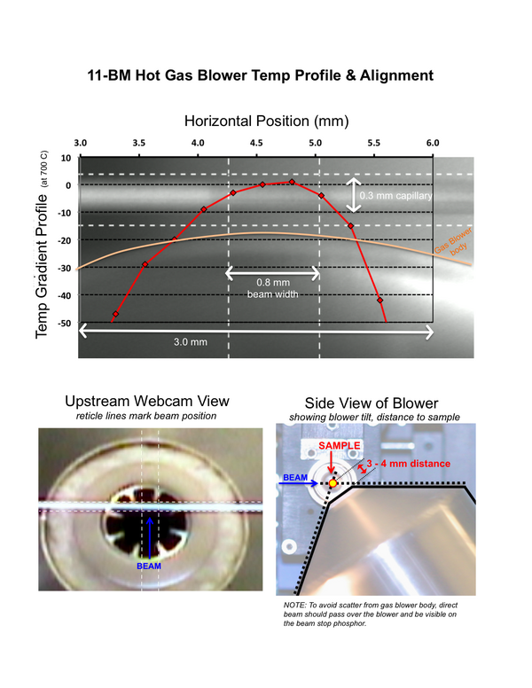
11-BM Hot Gas Blower Alignment
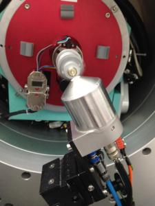
11-BM Hot Gas Blower Images
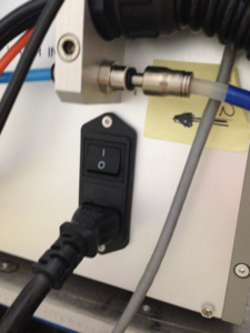
Mains power (black switch) and Water Flow Interlock Switch are located on the back of the control box.
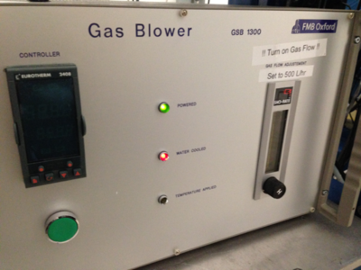
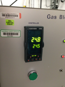
Turning on the Mains power and cooling water will turn the front LED lights Green and Red, respectively. Pressing the round GREEN button on the front will turn on the Eurotherm Temperature Controller
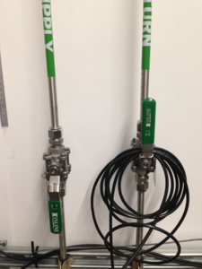
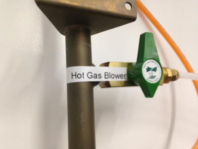
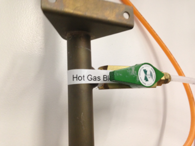
Make sure the the Air flow is turned on (Off/Closed at left, On/Open in the right image)
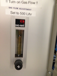
Now the Air flow should be at ~ 500 L/hr, and once aligned to the sample the Hot Gas Blower is ready to use.
Turning the Hot Gas Blower Off
When the blower is cool, you may turn off the mains power in the back of the controller.
IMPORTANT: When you are finished with the Hot Gas Blower, or want to switch to the N2 blower, TURN OFF/CLOSE the Air flow for the Hot Gas blower, and cover the mouth with foil or the lid. If left Open/On, the air steam from the Hot Gas blower can interfere with the N2 blower shield gas and result if icing problems when using the N2 blower.
Temperature Profile & Alignment
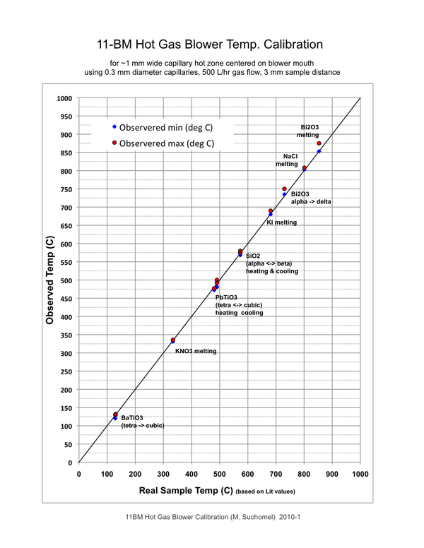
Temperature Calibration
Al2O3 Thermal Expansion
In-situ calibration of the hot gas blower was performed using the known thermal expansion of alumina (Al2O3) a & c unit cell parameters as a function of temperature.
Full powder diffraction patterns were collected for select "nominal" set temperatures between 100 - 950 C at 11-BM using a 0.5 mm diameter fused quartz capillary packed with Al2O3 powder (NIST SRM 676a).
Refinements were performed against data from each nominal temperature to determine a & c unit cell parameters.
Based on the initial room temperature (25 C) lattice values and published thermal expansion equations (J. Appl. Cryst. (1993). 26, 77-81 ), "real" observed sample temperatures were then calculated independently for each set of a & c unit cell terms.
Download the Open Office Worksheet here (Internal only): HighTempCalibration_ThermalExpansion.ods
Approximate room-temperature lattice parameters are:
a = 4.7592 A
c = 12.9934 A
The thermal expansion equation used for the a axis of Al2O3 (range 293-1900 K) is:
delta(a)/a (%) = -0.176 + (5.431E-4 * T) + (2.150-7 * T^2) - (2.810E-11 * T^3) (T/K)
The thermal expansion equation used for the c axis of Al2O3 (range 293-1900 K) is:
delta(c)/c (%) = -0.192 + (5.927E-4 * T) + (2.142E-7 * T^2) - (2.207E-11 * T^3) (T/K)
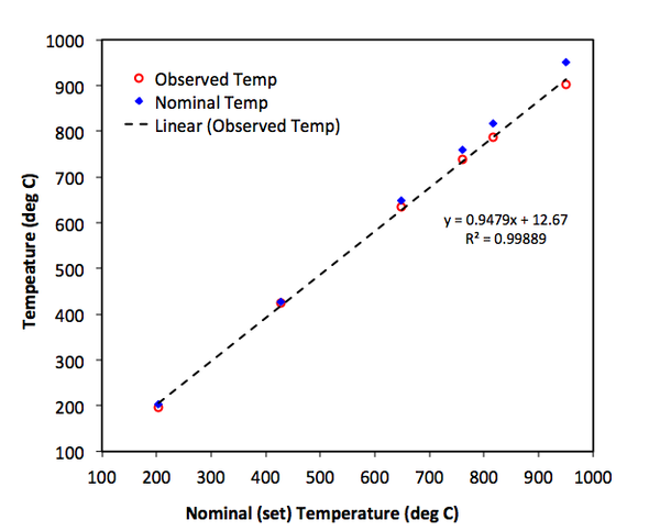
Finally, plotting observed vs nominal set temperatures for the Al2O3 data gives a correction curve and equation for other hot air blower measurements at 11-BM under similar experimental conditions.
These results (from July 2012) are shown below. These calibration data are kindly shared by Jae-Hyuk Her, GE Global Research.
Corrected temperature values calculated from calibration equation:
T_observed(K) = 0.9479*T_nominal(K) + 12.67

Nominal (Set) 	  Observed 	     Obs - Set
deg C	deg K	  deg C	 deg K		deg
 25	 298	   25	  295	  	  0
100	 373	   93	  366		 -7
200	 473	  188	  461		-12
300	 573	  283	  556		-17
400	 673	  378	  651		-22
500	 773	  472	  745		-28
600	 873	  567	  840		-33
700	 973	  662	  935		-38
800	1073	  757	 1030		-43
900	1173	  852	 1125		-48
950	1223	  899	 1172		-51
Phase Transitions
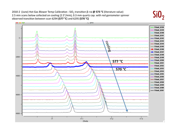
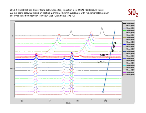
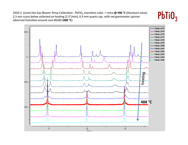
The temperature calibration of the hot gas blower was also studied using in-situ diffraction measurements of several known phase transitions. These results (from ~ 2011) are posted below.
