Difference between revisions of "34ID-E Coordinate Systems"
From 34-ID-E
Jump to navigationJump to search| Line 21: | Line 21: | ||
== Detector Coordinates == | == Detector Coordinates == | ||
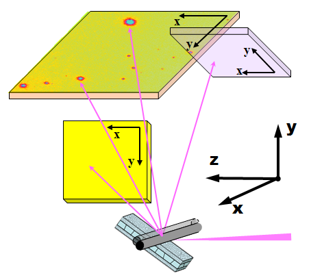
[[Image:Coordinates_beamline+detectors_3d.png|frame|left|Figure A.]] | |||
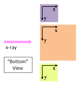
[[Image:Coordinates_detectors.png|frame|right|Figure B.]] | |||
Figure A (left): A 3D cartoon showing detector image coordinates and the beamline XYZ coordinate system. | |||
Figure B (right): 2D diagram showing relative positions and orientations of the images from the three detectors, arranged as if they are viewed from the sample, or from the bottom up. | |||
<br clear=all> | |||
== Coordinate Systems in Data Analysis == | == Coordinate Systems in Data Analysis == | ||
Revision as of 22:28, 4 October 2013
| (This article/section is incomplete, please check back again or help expanding it) |
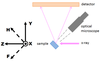
Beamline Coordinates
X-Y-Z
- X: radial direction of the ring, horizontal, pointing outboard to the doors.
- Y: vertically upward (against gravity).
- Z: along the x-ray beam
X-H-F
Because we routinely deal with motions in 45°-tilted directions, H and F are introduced as alternative coordinates to Y and Z:
- H: 45° upward-downstream (combination of +Y and +Z), this is the typical movement direction of the depth-profiling wire.
- F: 45° downward-downstream (combination of -Y and +Z), this is the "focus" direction of the sample under the optical microscope.
<math>H = \frac{1}{\sqrt{2}}(Y+Z)</math>
<math>F = \frac{1}{\sqrt{2}}(-Y+Z) </math>
Detector Coordinates
Figure A (left): A 3D cartoon showing detector image coordinates and the beamline XYZ coordinate system.
Figure B (right): 2D diagram showing relative positions and orientations of the images from the three detectors, arranged as if they are viewed from the sample, or from the bottom up.


