Difference between revisions of "Geometry parameters"
From 34-ID-E
Jump to navigationJump to searchm (→Usage) |
|||
| (One intermediate revision by the same user not shown) | |||
| Line 20: | Line 20: | ||
== Usage == | == Usage == | ||
{{Incomplete}} | |||
Geometry file | Geometry file | ||
| Line 28: | Line 30: | ||
* [[LaueGo]], the data analysis package | * [[LaueGo]], the data analysis package | ||
* [[ | * [[34ID-E Detectors]] | ||
* [[34ID E-station]] | * [[34ID E-station]] | ||
Latest revision as of 17:55, 16 August 2013
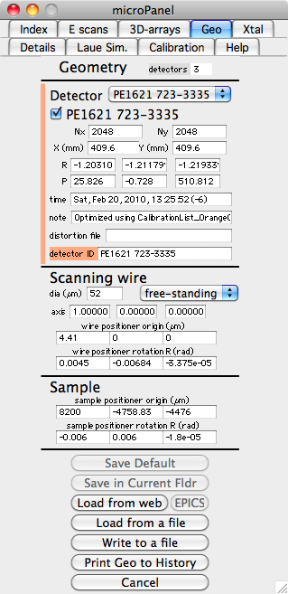
The geometry parameters defines the 3D spatial relationship between the x-ray beam, the sample, the depth-profiling wire, and the x-ray detectors in the experimental station. Their values are critical for the accuracy of any measurement. The parameters are calibrated regularly by the beamline staff.
Meaning of the Parameters
First note that the origin is the focal point of the x-ray beam and is usualy found using a 4-µm thick piece of Si. The beam-line coordinate system is X is out the door, Y is up, and Z is along the x-ray beam direction. Except for strain refinement, this is the main coordinate system.
- The size of the detector is given by four parameters, (Nx,Ny) are the number of raw un-binned pixels in the entire detector. The two parameters X(mm) and Y(mm) are the outside dimensions of the active area (not distance between middle of pixels). Together these four parameters locate a pixel on the detector.
- The detector position(s) are specifed using two vectors R and P. The base position of the detector is with the plane of the detector containing the origin, and the detector perpendicular to the incident beam. The detector is assumed centered on the incident beam with the detectors x-axis pointing in the +X direction and y-axis pointing in +Y direction. This is, of course, not a useful location for a detector. The actual detector position is obtained by then doing a translation of vector P followed by a rotation about vector R. R specifies a rotation about the direction of R, and size of the rotation is |R|, where |R| is in radians. The translation by P is applied first, followed by the rotation. The advantage of this order is that the z component of the P vector gives the distance of the detector center from the origin, and the x and y components show how far off-center of the detector is from a perpendicular line to the origin.
- The "detector ID" is a string that is unique to a detector and should be stored in each image. Thus the computer can associate a detector image with its geometry parameters. You can use the pop-up in the Geometry panel to view the values for all of the defined detectors.
- The Scanning wire parameters define the location and orientation of the wire. Although provisions exist for describing the wire as "free-standing" or "knife edge", only a free-standing wire exists. The "wire positioner at origin" is the wire-stage position that puts the wire center on the origin. The "axis" gives the direction of the wire axis on the wire-stage, and it will probably be {1,0,0}. The "wire positioner rotation" gives the orientation of the positioner, since the positioner is probably not perfectly aligned with the beam-line coordinates.
- The Sample parameters can be used to specify the origin of the the sample using the positioner, but these parameters are generally not used.
Usage
| (This article/section is incomplete, please check back again or help expanding it) |
Geometry file
"Geo" tab in LaueGo
See Also
- LaueGo, the data analysis package
- 34ID-E Detectors
- 34ID E-station
